


Overview
Amplitude modulation (AM) is a technique used in electronic communication, most commonly for transmitting information via a radio carrier wave. AM works by varying the strength of the transmitted signal in relation to the information being sent. For example, changes in the signal strength can be used to specify the sounds to be reproduced by a loudspeaker, or the light intensity of television pixels. (Contrast this with frequency modulation, also commonly used for sound transmissions, in which the frequency is varied; and phase modulation, often used in remote controls, in which the phase is varied)
In the mid-1870s, a form of amplitude modulation—initially called "undulatory currents"—was the first method to successfully produce quality audio over telephone lines. Beginning with Reginald Fessenden's audio demonstrations in 1906, it was also the original method used for audio radio transmissions, and remains in use today by many forms of communication—"AM" is often used to refer to the mediumwave broadcast band (see AM radio).
Modulation Index
It can be defined as the measure of extent of amplitude variation about an unmodulated maximum carrier. As with other modulation indices, in AM, this quantity, also called modulation depth, indicates by how much the modulated variable varies around its 'original' level. For AM, it relates to the variations in the carrier amplitude and is defined as:
So if h = 0.5, the carrier amplitude varies by 50% above and below its unmodulated level, and for h = 1.0 it varies by 100%. To avoid distortion in the A3E transmission mode, modulation depth greater than 100% must be avoided. Practical transmitter systems will usually incorporate some kind of limiter circuit, such as a VOGAD, to ensure this. However, AM demodulators can be designed to detect the inversion (or 180 degree phase reversal) that occurs when modulation exceeds 100% and automatically correct for this effect.
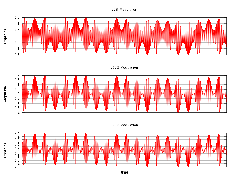
Variations of modulated signal with percentage modulation are shown below. In each image, the maximum amplitude is higher than in the previous image. Note that the scale changes from one image to the next.
Amplitude Demodulation
While the half-wave rectifier is very simple and does work, it isn't very efficient. It only uses half of the incoming ac cycle, and wastes all of the energy available in the other half. For greater efficiency, we would like to be able to utilize both halves of the incoming ac. One way to accomplish this is to double the size of the secondary winding and provide a connection to its center. Then we can use two separate half-wave rectifiers on alternate half-cycles, to provide full-wave rectification. The circuit is shown to the right.
Because both half-cycles are being used, the DC component of the output waveform is now 2vp/Your browser may not support display of this image. = 0.6366vp, where vp is the peak voltage output from half the transformer secondary winding, because only half is being used at a time.
This rectifier configuration, like the half-wave rectifier, calls for one of the transformer's secondary leads to be grounded. In this case, however, it is the center connection, generally known as the center tap on the secondary winding.
 |
The full-wave rectifier can still be configured for a negative output voltage, rather than positive. In addition, as shown to the right, it is quite possible to use two full-wave rectifiers to get outputs of both polarities at the same time.
The full-wave rectifier passes both halves of the ac cycle to either a positive or negative output. This makes more energy available to the output, without large intervals when no energy is provided at all. Therefore, the full-wave rectifier is more efficient than the half-wave rectifier. At the same time, however, a full-wave rectifier providing only a single output polarity does require a secondary winding that is twice as big as the half-wave rectifier's secondary, because only half of the secondary winding is providing power on any one half-cycle of the incoming ac.
Actually, it isn't all that bad, because the use of both half-cycles means that the current drain on the transformer winding need not be as heavy. With power being provided on both half-cycles, one half-cycle doesn't have to provide enough power to carry the load past an unused half-cycle. Nevertheless, there are some occasions when we would like to be able to use the entire transformer winding at all times, and still get full-wave rectification with a single output polarity.
As the spaces between each half-wave developed by each diode is now being filled in by the other diode the average DC output voltage across the load resistor is now double that of the single half-wave rectifier circuit and is about 0.637Vmax of the peak voltage, assuming no losses.
 |
The peak voltage of the output waveform is the same as before for the half-wave rectifier provided each half of the transformer windings have the same rms voltage value. To obtain a different d.c. voltage output different transformer ratios can be used, but one main disadvantage of this type of rectifier is that having a larger transformer for a given power output with two separate windings makes this type of circuit costly compared to a "Bridge Rectifier" circuit equivalent.
Full-Wave Bridge Rectifier
The four-diode rectifier circuit shown to the right serves very nicely to provide full-wave rectification of the ac output of a single transformer winding. The diamond configuration of the four diodes is the same as the resistor configuration in a Wheatstone Bridge. In fact, any set of components in this configuration is identified as some sort of bridge, and this rectifier circuit is similarly known as a bridge rectifier.
If you compare this circuit with the dual-polarity full-wave rectifier above, you'll find that the connections to the diodes are the same. The only change is that we have removed the center tap on the secondary winding, and used the negative output as our ground reference instead. This means that the transformer secondary is never directly grounded, but one end or the other will always be close to ground, through a forward-biased diode. This is not usually a problem in modern circuits.
 |
To understand how the bridge rectifier can pass current to a load in only one direction, consider the figure to the right. Here we have placed a simple resistor as the load, and we have numbered the four diodes so we can identify them individually.
During the positive half-cycle, shown in red, the top end of the transformer winding is positive with respect to the bottom half. Therefore, the transformer pushes electrons from its bottom end, through D3 which is forward biased, and through the load resistor in the direction shown by the red arrows. Electrons then continue through the forward-biased D2, and from there to the top of the transformer winding. This forms a complete circuit, so current can indeed flow. At the same time, D1 and D4 are reverse biased, so they do not conduct any current.
During the negative half-cycle, the top end of the transformer winding is negative. Now, D1 and D4 are forward biased, and D2 and D3 are reverse biased. Therefore, electrons move through D1, the resistor, and D4 in the direction shown by the blue arrows. As with the positive half-cycle, electrons move through the resistor from left to right.
In this manner, the diodes keep switching the transformer connections to the resistor so that current always flows in only one direction through the resistor. We can replace the resistor with any other circuit, including more power supply circuitry (such as the filter), and still see the same behavior from the bridge rectifier.
 |
 |
Current Flow in Brigde Rectifier
For both positive and negative swings of the transformer, there is a forward path through the diode bridge. Both conduction paths cause current to flow in the same direction through the load resistor, accomplishing full-wave rectification.
While one set of diodes is forward biased, the other set is reverse biased and effectively eliminated from the circuit.
 |
 |
Smoothing Capacitor
We saw in the previous section that the single phase half-wave rectifier produces an output wave every half cycle and that it was not practical to use this type of circuit to produce a steady DC supply. The full-wave bridge rectifier however, gives us a greater mean DC value (0.637 Vmax) with less superimposed ripple while the output waveform is twice that of the frequency of the input supply frequency. We can therefore increase its average DC output level even higher by connecting a suitable smoothing capacitor across the output of the bridge circuit as shown below.
Full-wave Rectifier with Smoothing Capacitor
 |
The smoothing capacitor converts the full-wave rippled output of the rectifier into a smooth DC output voltage. Two important parameters to consider when choosing a suitable a capacitor are its Working Voltage, which must be higher than the no-load output value of the rectifier and its Capacitance Value, which determines the amount of ripple that will appear superimposed on top of the DC voltage. Too low a value and the capacitor has little effect. As a general rule of thumb, we are looking to have a ripple voltage of less than 100mV peak to peak.
The main advantages of a full-wave bridge rectifier is that it has a smaller AC ripple value for a given load and a smaller reservoir or smoothing capacitor than an equivalent half-wave rectifier. Therefore, the fundamental frequency of the ripple voltage is twice that of the AC supply frequency (100Hz) where for the half-wave rectifier it is exactly equal to the supply frequency (50Hz). The amount of ripple voltage that is superimposed on top of the DC supply voltage by the diodes can be virtually eliminated by adding a much improved π-filter (pi-filter) to the output terminals of the bridge rectifier. This type of low-pass filter consists of two smoothing capacitors, usually of the same value and a choke or inductance across them to introduce a high impedance path to the alternating ripple component. Another more practical and cheaper alternative is to use a 3-terminal voltage regulator IC, such as a LM7805 which can reduce the ripple by more than 70dB (Datasheet) while delivering over 1amp of output current.